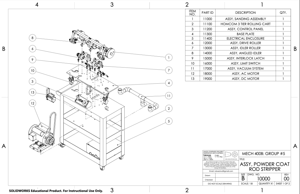
Automated Rod Stripper

This exciting project was carried out in fulfillment of my capstone project in collaboration with JSF Coatings.
JSF, a Victoria machine shop, was having issues with powder coat over-spray covering there part-hanging rods. This overspray interrupted the electrical grounding of parts. As powder coat adheres through static electricity, this grounding is vital to quality coating. Beyond this, overspray would often chip off in the furnace and fall on parts below, further impacting quality. As a solution, our capstone group developed an automated machine to strip over-spray off of hanging rods.
The solution developed is best understood through the following video.
The following information will provide a brief overview of this extensive project. For a more in-depth review, see the project report at the end of this page.
Background
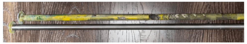
The powder coating rods range from 1/2″ to 7/8″ in diameter, had significant warpage, and have washers welded on the ends to hold them in place. Currently, JSF employees manually sand one side of these rods to clear overspray. This process is labour intensive, unsafe, and does not remove all the paint.
Various techniques to remove over spray were considered.
| Technique | Analysis |
| Burn off oven | Ruled out due high temperatures required and toxic fumes. |
| Rotary tumbler | Tests proved ineffective at removing powder coat. |
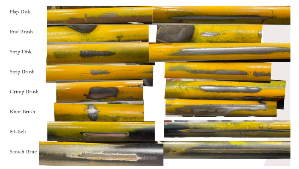
| Abrasive tool | Wire wheels, strip disks, flap disks, and sanding paper proved effective. |
Through tests with manual using abrasive tools, it was found that sanding belts were the most efficient.
Design
In our group, I lead the conceptualization, mechanical design, and operational analysis of the machine.
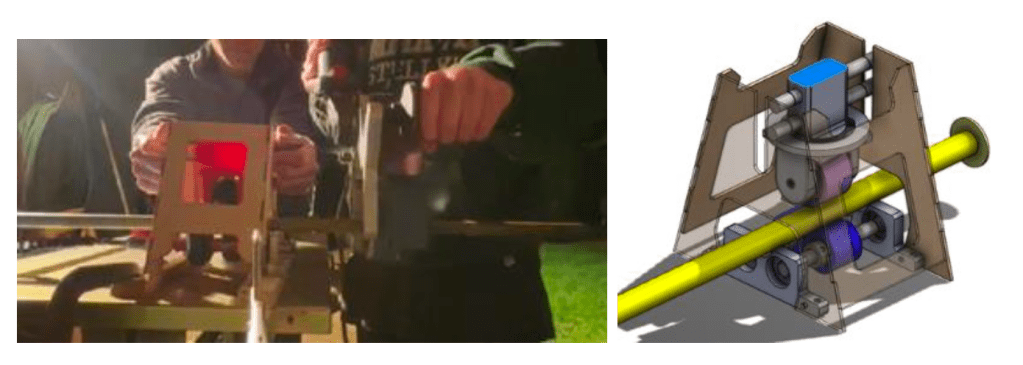
To perform the sanding operation, we had the option to move either the sanding tool along the rod, or actuate the rod past the sander. To keep the machines size down, I opted to actuate the rods. To perform this actuation, an initial design was developed to both rotate and linearly actuate rods through the use of helical rollers.
This design was eventually scraped due to its complexity, difficulty to mount a motor to shafts, and in-adaptability for multiple rod sizes. Instead, further research showed that powered parallel rollers with a singled angled idler would provide the motion we needed.
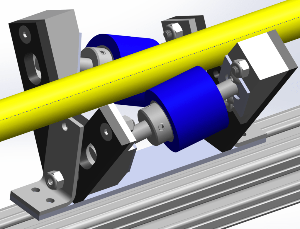
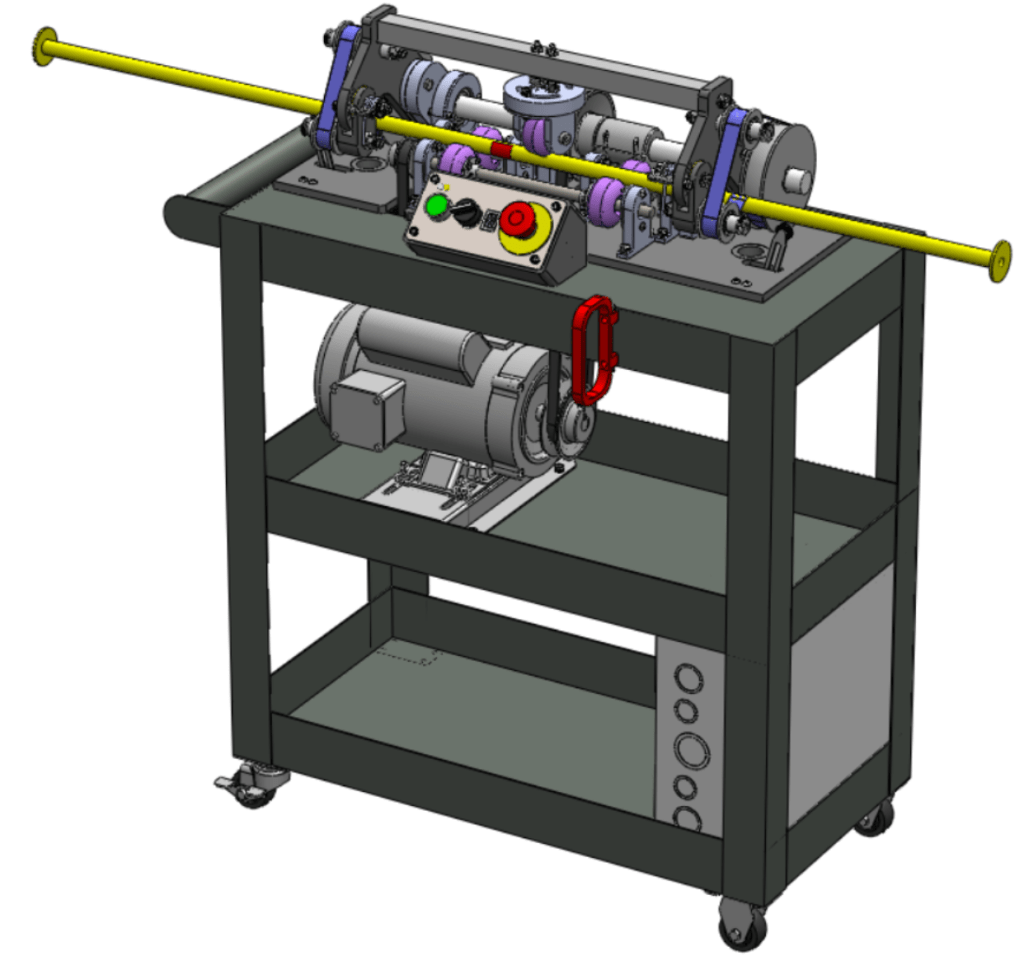
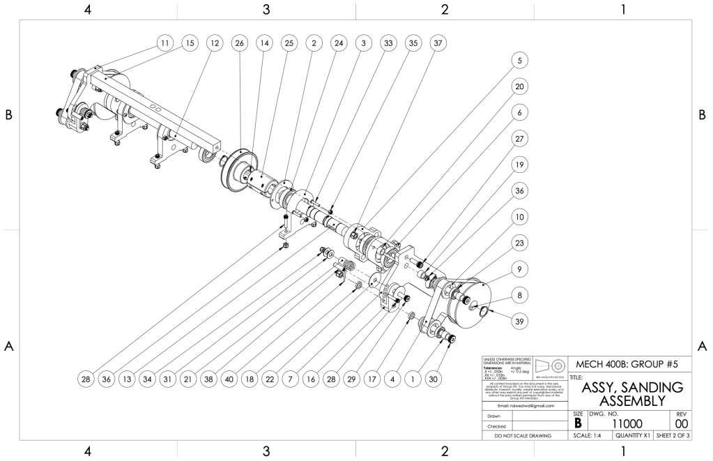
Next, the location and method of sanding had to be decided. Due to the washers on the ends of the rods, a simple through feed design was ruled out. Instead, dual sanding belts were selected that would allow the rod to track back and forth and sand right up to the washers. After several iterations, the final design developed is seen below.
The in line rollers are powered to provide rotation while the angled idler pushes downwards with springs and provides rotation. These springs both provide downwards pressure to hold the bar in place and allow for various bar sizes. The whole system swings down on to rods BBQ style, and swing arms with torsion springs deflect to allow the sanding belts to wrap around the bar and keep them under tension.
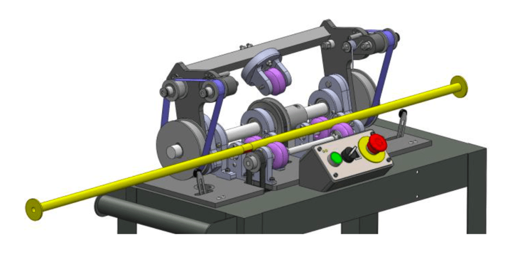
Sanding belts are powered by an AC motor. This motor rotates the main drive shaft that the system also pivots about to load bars. In line rollers are powered by a DC motor. To control the actuation direction, limit switches are hit by washers when sanding belts have reached the end of a rod. This provides indication to the DC motor to switch direction.
Testing
In-depth testing was completed thought this project to verify every principle and design concept. Initial tests were conducted to find the best abrasive tool.
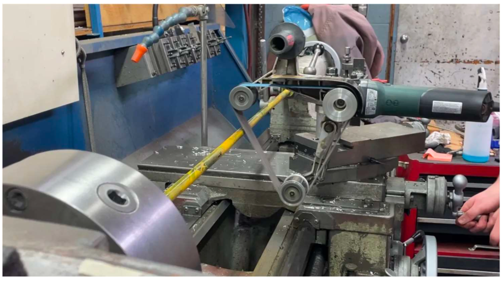
Tests were also completed with a manual sander and a mock angled idler set up to verify the desired motion and paint removal.
The result of final project testing was the successful cleaning of part hanging rods.